
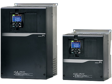
At the point where ease of use meets high performance
| 3-phase 200V | 0.4 - 55kW |
|---|---|
| 3-phase 400V | 0.75 - 315kW |


You should download this manual and carefully read it when using the STO function for functional safety.
| Model name(P1-☐☐☐-L) | 00044 | 00080 | 00104 | 00156 | 00228 | 00330 | 00460 | 00600 | 00800 | 00930 | 01240 | 01530 | 01850 | 02290 | 02950 | |||
|---|---|---|---|---|---|---|---|---|---|---|---|---|---|---|---|---|---|---|
| Applicable motor capacity (4 poles) (kW)*1 |
VLD | 0.75 | 1.5 | 2.2 | 3.7 | 5.5 | 7.5 | 11 | 15 | 18.5 | 22 | 30 | 37 | 45 | 55 | 75 | ||
| LD | 0.75 | 1.5 | 2.2 | 3.7 | 5.5 | 7.5 | 11 | 15 | 18.5 | 22 | 30 | 37 | 45 | 55 | 75 | |||
| ND | 0.4 | 0.75 | 1.5 | 2.2 | 3.7 | 5.5 | 7.5 | 11 | 15 | 18.5 | 22 | 30 | 37 | 45 | 55 | |||
| Output | Rated output current (A)*2 |
VLD | 4.4 | 8.0 | 10.4 | 15.6 | 22.8 | 33.0 | 46.0 | 60.0 | 80.0 | 93.0 | 124 | 153 | 185 | 229 | 295 | |
| LD | 3.7 | 6.3 | 9.4 | 12.0 | 19.6 | 30.0 | 40.0 | 56.0 | 73.0 | 85.0 | 113 | 140 | 169 | 210 | 270 | |||
| ND | 3.2 | 5.0 | 8.0 | 11.0 | 17.5 | 25.0 | 32.0 | 46.0 | 64.0 | 76.0 | 95.0 | 122 | 146 | 182 | 220 | |||
| Overload current rating | VLD | 110% 60sec / 120% 3sec | ||||||||||||||||
| LD | 120% 60sec / 150% 3sec | |||||||||||||||||
| ND | 150% 60sec / 200% 3sec | |||||||||||||||||
| Rated output voltage | Three-phase (3 wire) 200 to 240 V (Corresponding to the incoming voltage) | |||||||||||||||||
| Rated capacity (kVA) | 200V | VLD | 1.5 | 2.7 | 3.6 | 5.4 | 7.8 | 11.4 | 15.9 | 20.7 | 27.7 | 32.2 | 42.9 | 53.0 | 64.0 | 79.3 | 102 | |
| LD | 1.2 | 2.1 | 3.2 | 4.1 | 6.7 | 10.3 | 13.8 | 19.3 | 25.2 | 29.4 | 39.1 | 48.4 | 58.5 | 72.7 | 93.5 | |||
| ND | 1.1 | 1.7 | 2.7 | 3.8 | 6.0 | 8.6 | 11.0 | 15.9 | 22.1 | 26.3 | 32.9 | 42.2 | 50.5 | 63.0 | 76.2 | |||
| 240V | VLD | 1.8 | 3.3 | 4.3 | 6.4 | 9.4 | 13.7 | 19.1 | 24.9 | 33.2 | 38.6 | 51.5 | 63.6 | 76.9 | 95.1 | 123 | ||
| LD | 1.5 | 2.6 | 3.9 | 4.9 | 8.1 | 12.4 | 16.6 | 23.2 | 30.3 | 35.3 | 46.9 | 58.1 | 70.2 | 87.2 | 112 | |||
| ND | 1.3 | 2.0 | 3.3 | 4.5 | 7.2 | 10.3 | 13.3 | 19.1 | 26.6 | 31.5 | 39.4 | 50.7 | 60.6 | 75.6 | 91.4 | |||
| Input | Rated input AC voltage*3 | Main circuit power supply: Three-phase (3 wire) 200 to 240 V 50Hz/60Hz Control power supply : Single-phase supply 200 to 240 V 50Hz/60Hz |
||||||||||||||||
| Permissible AC voltage/ Frequency fluctuation*3 |
AC voltage: 170 to 264V 50/60Hz, Frequency: ±5% | |||||||||||||||||
| Power supply capacity (kVA)*4 | VLD | 2.0 | 3.7 | 4.8 | 7.1 | 10.4 | 15.0 | 20.9 | 27.3 | 36.3 | 42.2 | 56.3 | 69.4 | 84.0 | 104 | 134 | ||
| LD | 1.7 | 2.9 | 4.3 | 5.5 | 8.9 | 13.7 | 18.2 | 25.5 | 33.2 | 38.6 | 51.3 | 63.6 | 76.7 | 95.3 | 123 | |||
| ND | 1.5 | 2.3 | 3.7 | 5.0 | 8.0 | 11.4 | 14.6 | 20.9 | 29.1 | 34.5 | 43.1 | 55.4 | 66.3 | 82.6 | 99.8 | |||
| Carrier frequency variation*5 | VLD | 0.5 to 10.0kHz | ||||||||||||||||
| LD | 0.5 to 12.0kHz | |||||||||||||||||
| ND | 0.5 to 16.0kHz | |||||||||||||||||
| Starting torque*6 | 200%/0.3Hz | |||||||||||||||||
| Braking | Regenerative Braking | Internal BRD circuit (external discharge resistor value) | Ext. regen. braking unit | |||||||||||||||
| Minimum resistance value (Ω) | 50 | 50 | 35 | 35 | 35 | 16 | 10 | 10 | 7.5 | 7.5 | 5 | - | - | - | - | |||
| Protective structure | IP20 - UL Open Type | |||||||||||||||||
| Aprox. weight (kg) | 3 | 3 | 3 | 3 | 3 | 6 | 6 | 6 | 10 | 10 | 10 | 22 | 33 | 33 | 47 | |||
| Model name(P1-☐☐☐-H) | 00041 | 00054 | 00083 | 00126 | 00175 | 00250 | 00310 | 00400 | 00470 | 00620 | 00770 | 00930 | 01160 | 01470 | 01760 | 02130 | 02520 | 03160 | |||
|---|---|---|---|---|---|---|---|---|---|---|---|---|---|---|---|---|---|---|---|---|---|
| Applicable motor capacity (4 poles) (kW)*1 |
VLD | 1.5 | 2.2 | 3.7 | 5.5 | 7.5 | 11 | 15 | 18.5 | 22 | 30 | 37 | 45 | 55 | 75 | 90 | 110 | 132 | 160 | ||
| LD | 1.5 | 2.2 | 3.7 | 5.5 | 7.5 | 11 | 15 | 18.5 | 22 | 30 | 37 | 45 | 55 | 75 | 90 | 110 | 132 | 160 | |||
| ND | 0.75 | 1.5 | 2.2 | 3.7 | 5.5 | 7.5 | 11 | 15 | 18.5 | 22 | 30 | 37 | 45 | 55 | 75 | 90 | 110 | 132 | |||
| Output | Rated output current (A)*2 |
VLD | 4.1 | 5.4 | 8.3 | 12.6 | 17.5 | 25.0 | 31.0 | 40.0 | 47.0 | 62.0 | 77.0 | 93.0 | 116 | 147 | 176 | 213 | 252 | 316 | |
| LD | 3.1 | 4.8 | 6.7 | 11.1 | 16.0 | 22.0 | 29.0 | 37.0 | 43.0 | 57.0 | 70.0 | 85.0 | 105 | 135 | 160 | 195 | 230 | 290 | |||
| ND | 2.5 | 4.0 | 5.5 | 9.2 | 14.8 | 19.0 | 25.0 | 32.0 | 39.0 | 48.0 | 61.0 | 75.0 | 91.0 | 112 | 150 | 180 | 217 | 260 | |||
| Overload current rating | VLD | 110% 60sec / 120% 3sec | |||||||||||||||||||
| LD | 120% 60sec / 150% 3sec | ||||||||||||||||||||
| ND | 150% 60sec / 200% 3sec | ||||||||||||||||||||
| Rated output voltage | Three-phase (3 wire) 380 to 500 V (Corresponding to the incoming voltage) | ||||||||||||||||||||
| Rated capacity (kVA) |
400V | VLD | 2.8 | 3.7 | 5.7 | 8.7 | 12.1 | 17.3 | 21.4 | 27.7 | 32.5 | 42.9 | 53.3 | 64.4 | 80.3 | 102 | 122 | 148 | 175 | 219 | |
| LD | 2.1 | 3.3 | 4.6 | 7.6 | 11.0 | 15.2 | 20.0 | 25.6 | 29.7 | 39.4 | 48.4 | 58.8 | 72.7 | 93.5 | 111 | 135 | 159 | 201 | |||
| ND | 1.7 | 2.7 | 3.8 | 6.3 | 10.2 | 13.1 | 17.3 | 22.1 | 27.0 | 33.2 | 42.2 | 51.9 | 63.0 | 77.5 | 104 | 125 | 150 | 180 | |||
| 500V | VLD | 3.5 | 4.6 | 7.1 | 10.9 | 15.1 | 21.6 | 26.8 | 34.6 | 40.7 | 53.6 | 66.6 | 80.5 | 100 | 127 | 152 | 184 | 218 | 274 | ||
| LD | 2.6 | 4.1 | 5.8 | 9.6 | 13.8 | 19.0 | 25.1 | 32.0 | 37.2 | 49.3 | 60.6 | 73.6 | 90.9 | 117 | 139 | 169 | 199 | 251 | |||
| ND | 2.1 | 3.4 | 4.7 | 7.9 | 12.8 | 16.4 | 21.6 | 27.7 | 33.7 | 41.5 | 52.8 | 64.9 | 78.8 | 96.9 | 130 | 156 | 188 | 225 | |||
| Input | Rated input AC voltage*3 | Main circuit power supply: Three-phase(3 wire) 380 to 500 V 50Hz/60Hz Control power supply: Single-phase supply 380 to 500 V 50Hz/60Hz |
|||||||||||||||||||
| Permissible AC voltage/ Frequency fluctuation*3 |
AC voltage:323 to 550V 50/60 Hz, Frequency :±5% | ||||||||||||||||||||
| Power supply capacity (kVA)*4 |
VLD | 3.8 | 4.9 | 7.6 | 11.5 | 15.9 | 22.8 | 28.2 | 36.3 | 42.7 | 56.3 | 69.9 | 84.4 | 105 | 133 | 160 | 193 | 229 | 287 | ||
| LD | 2.9 | 4.4 | 6.1 | 10.1 | 14.5 | 20.0 | 26.3 | 33.6 | 39.1 | 51.8 | 63.5 | 77.2 | 95.3 | 123 | 145 | 177 | 209 | 263 | |||
| ND | 2.3 | 3.7 | 5.0 | 8.4 | 13.5 | 17.3 | 22.8 | 29.1 | 35.4 | 43.6 | 55.4 | 68.1 | 82.6 | 102 | 136 | 163 | 197 | 236 | |||
| Carrier frequency variation*5 | VLD | 0.5 to 10.0kHz | 0.5 to 8.0kHz | ||||||||||||||||||
| LD | 0.5 to 12.0kHz | 0.5 to 8.0kHz | |||||||||||||||||||
| ND | 0.5 to 16.0kHz | 0.5 to 10.0kHz | |||||||||||||||||||
| Starting torque*6 | 200%/0.3Hz | 180%/0.3Hz | |||||||||||||||||||
| Braking | Regenerative Braking | Internal BRD circuit (external discharge resistor value) | *7 | Ext. regen. braking unit | |||||||||||||||||
| Minimum resistance value (Ω) | 100 | 100 | 100 | 70 | 70 | 35 | 35 | 24 | 24 | 20 | 15 | 15 | 10 | 10 | - | - | - | - | |||
| Protective structure | IP20 – UL Open Type | ||||||||||||||||||||
| Aprox. weight (kg) | 3 | 3 | 3 | 3 | 6 | 6 | 6 | 8.5 | 8.5 | 8.5 | 22 | 31 | 31 | 31 | 41 | 41 | 53 | 53 | |||
| Model name(P1-☐☐☐-H) | 03720 | 04320 | 04860 | 05200 | 05500 | 06600 | |||
|---|---|---|---|---|---|---|---|---|---|
| Applicable motor capacity (4 poles) (kW)*1 |
VLD | 185 | 200 | 220 | 250 | - | - | ||
| LD | 185 | 200 | 220 | 250 | 280 | 355 | |||
| ND | 160 | 185 | 200 | 220 | 250 | 315 | |||
| Output | Rated output current (A)*2 |
VLD | 372 | 432 | 486 | 520 | - | - | |
| LD | 341 | 395 | 446 | 481 | 550 | 660 | |||
| ND | 310 | 370 | 405 | 450 | 500 | 600 | |||
| Overload current rating | VLD | 110% 60sec / 120% 3sec | - | - | |||||
| LD | 120% 60sec / 150% 3sec | ||||||||
| ND | 150% 60sec / 200% 3sec | ||||||||
| Rated output voltage | Three-phase (3 wire) 380 to 500 V (Corresponding to the incoming voltage) | ||||||||
| Rated capacity (kVA) |
400V | VLD | 258 | 299 | 337 | 360 | - | - | |
| LD | 236 | 274 | 309 | 333 | 381 | 457 | |||
| ND | 215 | 256 | 281 | 312 | 346 | 416 | |||
| 500V | VLD | 322 | 374 | 421 | 450 | - | - | ||
| LD | 295 | 342 | 386 | 417 | 476 | 572 | |||
| ND | 268 | 320 | 351 | 390 | 433 | 520 | |||
| Input | Rated input AC voltage*3 | Main circuit power supply: Three-phase(3 wire) 380 to 500 V 50Hz/60Hz Control power supply: Single-phase supply 380 to 500 V 50Hz/60Hz |
|||||||
| Permissible AC voltage/ Frequency fluctuation*3 |
AC voltage:323 to 550V 50/60 Hz, Frequency :±5% | ||||||||
| Power supply capacity (kVA)*4 |
VLD | 338 | 392 | 441 | 472 | - | - | ||
| LD | 310 | 358 | 405 | 436 | 499 | 599 | |||
| ND | 281 | 336 | 368 | 408 | 454 | 544 | |||
| Carrier frequency variation*5 | VLD | 0.5 to 8.0kHz | - | - | |||||
| LD | 0.5 to 8.0kHz | ||||||||
| ND | 0.5 to 10.0kHz | ||||||||
| Starting torque*6 | 180%/0.3Hz | ||||||||
| Braking | Regenerative Braking | Ext. regen. braking unit | |||||||
| Minimum resistance value (Ω) | - | - | - | - | - | - | |||
| Protective structure | IP20 – UL Open Type | ||||||||
| Aprox. weight (kg) | 95 | 125 | 125 | 125 | 125 | 170 | |||
| Items | General Specifications | |||
|---|---|---|---|---|
| PWM system | Sine-wave PWM system | |||
| Output frequency range*1 | 0.00 to 590.00Hz | |||
| Frequency accuracy | For the highest frequency, digital ±0.01%, analogue ±0.2% (25±10℃) | |||
| Frequency resolution | Digital: 0.01Hz, Analogue: Max. frequency / 4000 (Ai1 terminal / Ai2 terminal: 12bit / 0 to +10V or 0 to +20mA, Ai3 terminal: 12bit / -10 to +10V) | |||
| Control system*2 | IM | V/f control (constant torque / reduced torque / free), Automatic boost control, V/f control with encoder (constant torque / reduced torque / free), Automatic boost control with encoder, Cascade type sensorless vector control, 0Hz sensorless vector control, Cascade type vector control with encoder (position and torque). | ||
| SM/PMM | Methods of synchronous startup for vectorless smart control / Methods of IVMS startup for vectorless smart control | |||
| Speed fluctuation*3 | ±0.5% (sensorless vector control) | |||
| Acceleration / deceleration time | 0.00 to 3600.00s (Linear, S-curve, U-curve, Inverted-U-curve, EL-S-curve) | |||
| Display | Output frequency, Output current, output torque, trip history, input/output terminal function, input/output power*4, PN voltage, etc. | |||
| Start functions | DC braking after the start, matching frequency after the start, active frequency matching start, Low-voltage start, retry restart. | |||
| Stop functions | After free run stop, deceleration stop; DC braking or external DC braking operation (Braking force, time, adjustment of operation speed) | |||
| Stall prevention function | Overload limit function, overcurrent supression, overvoltage suppresion function | |||
| Protection functions*5 | Overcurrent error, overload error, brake resistor overload, overvoltage error, memory error, undervoltage error, current detector error, CPU error, external trip error, USP error, ground error, supply overvoltage error, power loss error, temperature detector error, Cooling-fan rotation speed decrease, temperature error, phase input error, IGBT error, phase output error, thermistor error, brake error, low-speed range overload error, inverter overload, RS485communication error, RTC error etc. | |||
| Other functions | V/f free setting (7 points), upper and lower frequency limit, frequency jump, curve acceleration and deceleration, manual torque boost, energy saving operation, analogue output adjustment, minimum speed, carrier frequency adjustment, motor electronic thermal function(free is possible), inverter thermal function, external start-end(speed and rate), frequency input selection, trip retry, restart stop, various signal output, initialization setting, PID control, auto-decel at shut-off, brake control function, commercial switching function, auto-tuning (on/offline) etc. | |||
| Input | Frequency setting | Panel | Up, down left and right keys to the set parameter. | |
| External signal*6 | Ai1 / Ai2 terminal (Current and Voltage is able to switched.) | 0 to 10Vdc (input impedance: 10kΩ) / 0 to 20mA (input impedance: 100Ω) | ||
| Ai3 terminal | -10 to +10Vdc (Input impedance: 10kΩ) | |||
| Multi-speed terminal | 16multi-speed (With the use of the intelligent input terminal) | |||
| Pulse train-input | Maximum 32kHz ×2 | |||
| External port | RS485serial communication (Protocol: Modbus-RTU, Maximum: 115.2kbps) | |||
| Forward / reverse Start / stop |
Panel | By RUN / Stop key (With the set parameter, forward / reverse can be switched) | ||
| External signal | Forward (FW) / Reverse (RV) / 3-wire input allowed (STA,STP,FR) (When input terminal functions are assigned) | |||
| External port | RS485serial communication (Protocol: Modbus-RTU, Maximum: 115.2kbps) | |||
| Intelligent input terminals | 11 terminals (A or B terminal accept a pulse train) | |||
| FW (Forward rotation) / RV (Reverse rotation), CF1 to 4 (Multi-speed 1 to 4), SF1 to 7 (Multi-speed bit 1 to 7), ADD (Trigger for frequency addition), SCHG (Command change), STA (3-wire start) / STP (3-wire stop) / FR (Forward / reverse by 3-wire), AHD (Analogue command holding), FUP (Remote control up) / FDN (Remote control down), UDC (Remote data clearance), F-OP(Forcible operation), SET (2nd-motor), RS (Reset), JG (Jogging), DB (External DC braking), 2CH (2-stage acc / decel), FRS (Free-run stop), EXT (External trip), USP (Unattended start protection), CS (Commercial power supply switching), SFT (Software lock), BOK (Braking confirmation), OLR (Overload restriction selection), KHC (Accumulated input power clear), OKHC (Accumulated input), PID (PID1 disable), PIDC (PID1 integration reset), PID2 (PID2 disable), PIDC2 (PID2 integration reset), SVC1 to 4 (PID1 multistage target value 1 to 4), PRO (PID gain change), PIO1 (PID output change), SLP (SLEEP trigger) / WAKE (WAKE trigger), TL (Enable torque limit), TRQ1/2 (Torque limit 1/2), PPI (P/PI switching), CAS (Control gain switching), FOC (Forcing), ATR (Enable torque command input), TBS (Enable torque bias), LAC (Acceleration / Deceleration cancellation), Mi1 to 11 (General-purpose input1 to 11), PCC (Pulse counter clearance), ECOM (EzCOM activation), PRG (EzSQ programme start), HLD (Acc / decel stop), REN (Motion enable signal), DISP (Display lock), PLA (Pulse train input A), PLB (Pulse train input B), DTR (Data trace start), DISP (Display lock), SON (servo on), ORT (orientation), PCLR (Clearance of position deviation), STAT (pulse train position command input enable), PUP (Position bias (ADD)), PDN (Position bias (SUB)), CP1 to 4 (Multistage position settings selection 1 to 4), ORL (Limit signal of Homing function), ORG (Start signal of Homing function), FOT (Forward Over Travel), ROT (Reserve Over Travel), SPD (speed / position switching), PSET (Position data presetting), | ||||
| Backup supply terminal | P+/P-: DC24V input (Input allowable voltage: 24V±10%) | |||
| STO input terminal | 2 terminals (Simultaneous input) | |||
| Thermistor input terminal | 1 terminal (PTC / NTC resistor allowed) | |||
| Output | Intelligent output terminals | Transistor output terminal 5, 1a contact relay 1 point, 1c contact relay 1 point | ||
| Intelligent alarm relay (1a, 1c) | RUN (While in run), FA1 to 5 (Reached frequency signal), IRDY (Inverter ready), FWR (Forward rotation), RVR (Reverse rotation), FREF (panel frequency reference), REF (panel motion operation), SETM (2nd-motor selected), AL (Alarm signal), MJA (Major failure signal), OTQ (Over-torque), IP (Power loss), UV (Undervoltage), TRQ (Torque limited), IPS (Decel. Power loss), RNT (RUN time exceeded), ONT (ON time exceeded), THM (Motor electronic thermal warning), THC (Electronic thermal warning), WAC (Capacitor life warning), WAF (Cooling-fan life warning), FR (Operation signal), OHF (heat sink overheat warning), LOC / LOC2 (Low-current indication signal), OL / OL2 (Overload warning signal 1/2), BRK (Brake release), BER (Brake error), ZS (0Hz detection signal), OD / OD2 (Output deviation for PID control), FBV / FBV2 (PID feedback comparison), NDc (Communication disconnection), Ai1Dc / Ai2Dc / Ai3Dc (Analogue Ai1 / Ai2 / Ai3 disconnection), WCAi1 / WCAi2 / WCAi3 (Window comparator Ai1 / Ai2 / Ai3), LOG1 to 7 (logical operation result 1 to 7), MO1 to 7 (General-output 1 to 7), OVS (Over-Voltage power supply), PCMP (Pulse counter compare output), WFT (Trace function waiting for trriger), TRA (Trace function data logging), PDD (Position deviation over), POK (Positioning completed), etc. | |||
| EDM output terminal | Functional safety diagnostic output | |||
| Output terminal monitor*7 | The data of the monitor can be selected by the parameter of the output. | |||
| EMC filter activation*8 | EMC filter can be activated (method to switch bares ) | |||
| PC external access | USB Micro-B | |||
| Environment | Ambient temperature*9 | -10 to 50℃ (ND), -10 to 45℃ (LD), -10 to 40℃ (VLD) | ||
| Storage temperature*10 | −20 to 65℃ | |||
| Level of humidity | 20 to 90%RH (No condensation allowed) | |||
| Vibration tolerance*11 | P1-00044-L (P1-004L) to P1-01240-L (P1-220L), P1-00041-H (P1-004H) to P1-00620H (P1-220H) | 5.9m/s² (0.6G), 10 to 55Hz | ||
| More than P1-01530-L (P1-300L), More than P1-00770-H (P1-300H) | 2.94m/s² (0.3G), 10 to 55Hz | |||
| Installation Place*12 | A maximum altitude of 1000m, without gases or dust. | |||
| Components life span | Main circuit smoothing capacitors is 10 years. / Cooling-fan is 10 years. | |||
| Conformity standars*13 | UL, cUL, CE marking, RCM, KC (planned), EAC (planned), NK (planned), functional safety (STO: SIL3, Cat 3/PLe) | |||
| Optional slots | 3 ports | |||
| Option | Input/ouput | Analogue input / output option | ||
| Communication | Ethernet (Modbus TCP), EtherCAT, PROFIBUS-DP, PROFINET | |||
| Feedback | Line driver input (RS422) | |||
| Other optional components | Braking resistor, AC reactor, noise filter, operator cable, harmonics suppresion unit, noise filter, LCRfilter, analog panel, regenerative braking unit, PC software ProdriveNext, relay expansion terminal board | |||