
At the point where ease of use meets high performance
| 3-phase 200V | 0.4 - 55kW |
|---|---|
| 3-phase 400V | 0.75 - 315kW |
You should download this manual and carefully read it when using the STO function for functional safety.
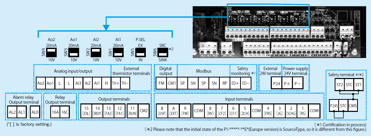
| Indication | Name of switch | Description (before shipment: underlined part) |
|---|---|---|
| Ai1(SW1) | Analog input 1 change | Change the input specification of Analog input 1 (Ai1 terminal). 10V: Voltage input is available. 20mA: Current input is available. |
| Ai2(SW2) | Analog input 2 change | Change the input specification of Analog input 2 (Ai2 terminal). 10V: Voltage input is available. 20mA: Current input is available. |
| Ao1(SW3) | Analog output 1 change | Change the output specification of Analog output 1 (Ao1 terminal). 10V: Voltage output is applied. 20mA: Current output is applied. |
| Ao2(SW4) | Analog output 2 change | Change the output specification of Analog output 2 (Ao2 terminal). 10V: Voltage output is applied. 20mA: Current output is applied. |
| P.SEL(SW5) | Change of the power supply method to input terminals | Change the power supply method to input terminals. IN: Activate input terminals by an internal power source. EX: Activate input terminals by inputting an external power source.(For EX, power supply is required between input terminals and COM.) |
| SRC/SINK(SW6) | Input terminal Sink/Source logic switching | Sink or source logic of the input terminal is switched. This is enabled when SW5 is IN. SINK: Switch to Sink logic. SRC: Switch to Source logic. |
| Symbol | Terminal name | Description | Electric characteristics | |||||||||||
|---|---|---|---|---|---|---|---|---|---|---|---|---|---|---|
| Voltage/current switchable analog input/output terminal | Power supply | L | COM for analog power supply | COM terminals for analog input terminals (Ai1,Ai2,Ai3) and analog output terminals (Ao1,Ao2). Two L terminals are available. | - | |||||||||
| H | Speed setting power supply | DC10V power supply. Used for voltage input with analog input terminals (Ai1,Ai2,Ai3) using a variable resister. | Max. allowable input current 20mA | |||||||||||
| Analog input | Ai1 | Analog input terminal 1 (Voltage/current selector SW1) | Either Ai1 or Ai2 can be used by switching the selector switch to DC0 to 10V voltage input or 0-to 20mA current input. Used as speed input and feedback input. | For voltage input: • Input impedance Approx.10kΩ • Allowable input voltage DC-0.3V to 12V For current input: • Input impedance Approx.100Ω • Max. allowable input current 24mA |
||||||||||
| Ai2 | Analog input terminal 2 (Voltage/current selector SW2) | |||||||||||||
| Ai3 | Analog input terminal 3 | DC-10 to 10V voltage input is available. Used as speed input and feedback input. | Voltage input only: • Input impedance Approx.10kΩ • Allowable voltage input DC-12V to 12V |
|||||||||||
| Analog output | Ao1 | Analog output terminal 1 (Voltage/current selector SW3) | Either Ao1 or Ao2 can be used as an output for inverter monitoring data by switching the selector switch to DC0 to 10V voltage output or 0 to 20mA current output. | For voltage output: • Max. allowable output current 2mA • Output voltage accuracy ±10% (Ambient temperature: 25±10 degrees C) For current input: • Allowable load impedance 250Ω or less • Output current accuracy ±20% (Ambient temperature: 25±10 degrees C) |
||||||||||
| Ao2 | Analog output terminal 2 (Voltage/current selector SW4) | |||||||||||||
| 24V power supply | Power input | P24 | 24V output power source terminal | This terminal supplies DC24V power for contact signals. | Max. output 100mA | |||||||||
| P+ | Terminal for external 24V input (24V) | Input external DC24V power supply to the inverter. Inputting 24V power supply can change parameter settings and perform optional communication operations without control power supply. | Allowable input voltage DC24V±10% Max. allowable current 1A | |||||||||||
| P- | Terminal for external 24V input (0V) | |||||||||||||
| Intelligent input terminal | Digital input | Contact point | 9 8 7 6 5 4 3 2 1 |
Input terminal | Terminal functions are selectable according to the parameter settings for each terminal. Switching SW6 to SRC or SINK allows you to select SINK or Source logic. |
Voltage between each input and COM terminals • ON voltage Min.DC18V • OFF voltage Max.DC3V • Max. allowable voltage DC27V • Load current 5.6mA (at DC27V) |
||||||||
| Pulse | A | Pulse input-A | This is a terminal for pulse input. A and B terminals can be used also as an input terminal. Terminal functions are selectable according to the parameter settings for each terminal. The maximum input pulse rate is 32kpps. |
Voltage between an input and COM terminals • ON voltage Min.DC18V • OFF voltage Max.DC3V • Max. allowable voltage DC27V • Load current 5.6mA (at DC27V) • Max input pulse rate 32kpps |
||||||||||
| B | Pulse input-B | |||||||||||||
| Common | COM | Input (common) | This is a common terminal for digital input terminals (1,2,3,4,5,6,7,8,9,A and B). Three COM terminals are available. | |||||||||||
| Intelligent output terminals | Digital output | Open collector | 15 14 13 12 11 |
Output terminal | Terminal functions are selectable according to the parameter settings for each terminal.This is available for both SINK and Source logics. | Open collector output Between each terminal and CM2 • Voltage drop when turned on:4V or less • Max. allowable voltage 27V • Max. allowable current 50mA |
||||||||
| CM2 | Output (common) | This is a common terminal for output terminals 11 to 15. | ||||||||||||
| Relay | 16A 16C |
1a relay terminal | Relays for A contact output | Maximum contact capacity • AC250V, 2A (resistance) • AC250V, 1A (inductive load) (Minimum contact capacity) • DC1V, 1mA |
||||||||||
| AL0 AL1 AL2 |
1c relay terminal | Relays for C contact output | Maximum contact capacity AL1/AL0: • AC250V, 2A (resistance) • AC250V, 0.2A (inductive load) AL2/AL0: • AC250V, 1A (resistance) • AC250V, 0.2A (inductive load) Minimum contact capacity (common) • AC100V, 10mA • DC5V, 100mA |
|||||||||||
| FM output terminal | FM output | Monitor output | FM | Digital monitor (voltage) | Digital monitor output is selectable from PWM output with 6.4ms cycle or pulse output with a variable duty cycle of approx. 50%. | Pulse train output DC0 to 10V • Max. allowable output current 1.2mA • Maximum frequency 3.60kHz |
||||||||
| CM1 | COM for digital monitor | This is a common terminal for digital monitor.This is also used as 0V reference potential for P24. | ||||||||||||
| Thermistor terminal | Analog input | TH+ | External thermistor input | Connect to an external thermistor to make the inverter trip if an abnormal temperature is detected. Connect the thermistor to TH+ and TH-. The impedance to detect temperature errors can be adjusted within the range 0Ω to 9,999Ω. [Recommended thermistor properties] Allowable rated power: 100 mW or more Impedance at temperature error: 3kΩ |
DC0 to 5V[Input circuit]
|
|||||||||
| TH- | Common terminal for external thermistor input | |||||||||||||
| RS485 communication | Serial communication | SP SN RP (CM1) |
MODBUS terminal (RS-485) |
|
Termination resistor (120Ω) integrated Enabled: RP-SN shorted Disabled: RP-SN opened |
|||||||||
| Safety terminals | Power supply for Safety | P24S | 24V output power source terminal | DC24V power supply for ST1/ST2 terminals. Using in source logic, this terminal becomes input COM. |
Max. allowable output current 20mA. | |||||||||
| CMS | COM terminal for functional safety | COM terminal for ST1/ST2 terminals. Using in sink logic, this terminal becomes input COM. |
||||||||||||
| STC | Logic switching terminal | Using ST1/ST2 in source logic, connect STC and CMS. Using ST1/ST2 in sink logic, connect STC and P24S. Using external power supply, connect external circuit to STC. |
||||||||||||
| Input | STO functions |
ST1 | STO input1 | Redundancy input terminals of the STO. For STO function, input to both terminals. |
Voltage between each input and P24S or between each input and CMS. • ON voltage Min.DC18V • OFF voltage Max.DC3V • Max. allowable voltage DC27V • Load current 5.6mA (at DC27V) |
|||||||||
| ST2 | STO input2 | |||||||||||||
| Monitoring | Open collector | ED+ | Output terminal for monitoring | Monitoring terminals for STO operation. This terminal can not be used for safety function operation. |
Open collector output between ED+ and ED-. • Voltage drop when turned on:4V or less • Max. allowable voltage 27V • Max. allowable current 50mA |
|||||||||
| ED- | Output COM terminal for monitoring | |||||||||||||
![DC0 to 5V[Input circuit]](/english/products/inv/sjp1/image/control2.png)