
At the point where ease of use meets high performance
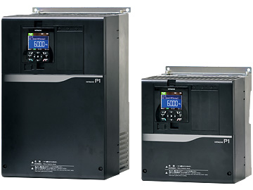
| 3-phase 200V | 0.4 - 55kW |
|---|---|
| 3-phase 400V | 0.75 - 315kW |


You should download this manual and carefully read it when using the STO function for functional safety.
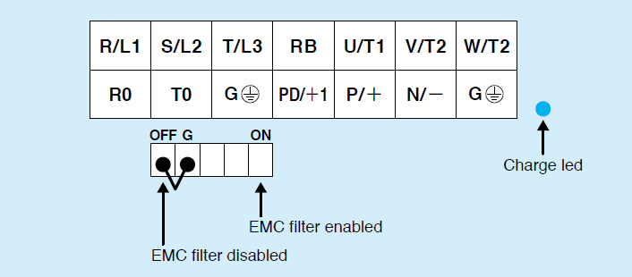
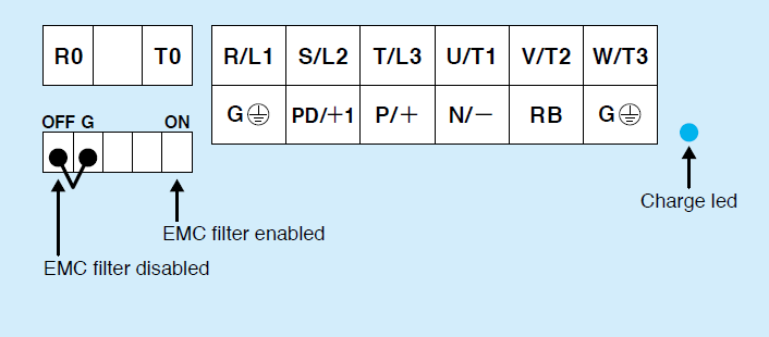
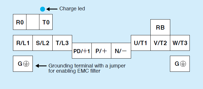
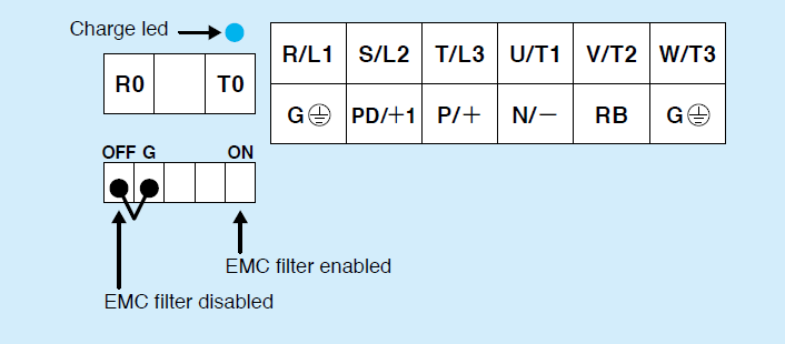
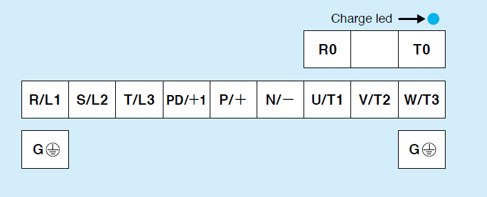
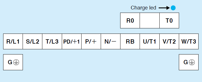
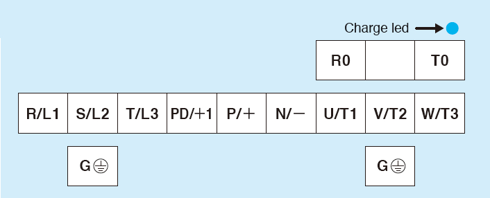
| Terminal Symbol | Terminal Name |
|---|---|
| R/L1, S/L2, T/L3 | Main power supply input terminals |
| P/+, N/− | External braking unit connection terminals |
| U/T1, V/T2, W/T3 | Inverter output terminals |
| G | Ground connection terminal |
| PD/+1, P/+ | DC reactor connection terminals |
| R0, T0 | Control power supply input terminals |
| P/+, RB | External braking resistor connection terminals |
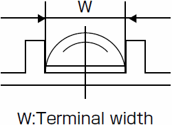
| Model | Screw diameter | Ground Screw diameter | Terminal width (mm) | Terminal Arrangement |
|---|---|---|---|---|
| P1-00044-LFF to P1-00228-LFF / P1-00041-HFF to P1-00126-HFF |
M4 | M4 | 10 | Figure 1 |
| P1-00330-LFF, P1-00460-LFF / P1-00175-HFF, P1-00250-HFF |
M5 | M5 | 13 | Figure 2 |
| P1-00600-LFF, P1-00310-HFF | M6 | M6 | 16.5 | Figure 2 |
| P1-00800-LFF, P1-00930-LFF | M6 | M6 | 23 | Figure 3 |
| P1-01240-LFF | M8 | M6 | 23 | Figure 3 |
| P1-00400-HFF to P1-00620-HFF | M6 | M6 | 16.5 | Figure 4 |
| P1-01530-LFF | M8 | M6 | 22 | Figure 5 |
| P1-01850-LFF, P1-02290-LFF | M8 | M8 | 29 | Figure 5 |
| P1-02950-LFF | M10 | M8 | 40 | Figure 5 |
| P1-00770-HFF | M6 | M6 | 22 | Figure 6 |
| P1-00930-HFF to P1-01470-HFF | M8 | M8 | 29 | Figure 6 |
| P1-01760-HFF, P1-02130-HFF | M10 | M8 | 29 | Figure 7 |
| P1-02520-HFF, P1-03160-HFF | M10 | M8 | 40 | Figure 5 |
Note:For P1-01760-HFF to P1-03160-HFF, Please contact your service or sales dept.