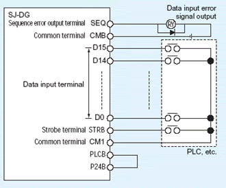
Output frequency, acceleration time, deceleration time, torque limit, and orientation position *1 can be set by a digital output device such as PLC, etc. (Binary or BCD)

| Item | Mode 1 | Mode 2 |
|---|---|---|
| D15 | Data classification code | Setting data Data can be set by either 16-bit binary or 4-digit BCD. |
| D14 | ||
| D13 | ||
| D12 | ||
| D11 | ||
| D10 | ||
| D9 | ||
| D8 | ||
| D7 | Setting data Data can be set by either 16-bit binary or 4-digit BCD. (Input data is divided into upper 8-bit and lower 8-bit.) |
|
| D6 | ||
| D5 | ||
| D4 | ||
| D3 | ||
| D2 | ||
| D1 | ||
| D0 |
| Item | Specification | ||
|---|---|---|---|
| Input | Data setting signal | NO contact input (sink/ source compatible) |
D0, D1, … between D15 and PLCB |
| Strobe signal | Between STRB and PLCB | ||
| Output | Sequence error signal (Data input error signal) | Open collector output (sink/ source compatible) |
DC+27V 50mA max., between SEQ and CMB |
| Power supply | Power supply for interface | DC+24V 90mA max., between P24B and CM1 | |