![]()
Earth Leakage Breakers : E Series
EB-50E, EB-100E, EX30, EX50, EX50B, EX50C, EX100, EX100B
| TYPE | EB-50E | EB-100E | EX30 | EX50 | EX50B | EX50C | EX100 | EX100B | ||||
|---|---|---|---|---|---|---|---|---|---|---|---|---|
| Phase- wiring Sysytem | 1φ2W | 3φ3W 1φ3W 1φ2W |
3φ3W 1φ3W 1φ2W |
3φ3W 1φ3W 1φ2W |
3φ3W 1φ3W 1φ2W |
3φ3W 1φ3W 1φ2W |
3φ3W 1φ3W 1φ2W |
3φ3W 1φ3W 1φ2W |
3φ3W 1φ3W 1φ2W |
|||
| Numner of Poles | 2 | 3 | 3 | 3 | 3 | 3 | 3 | 3 | 3 | |||
| Rated Voltage (AC V) | 100 – 200 | 100 – 200 | 100 – 200 | 200 – 440 | 100 – 200 | 200 – 440 | 100 – 200 | 200 – 440 | ||||
| Rated Current (A) (Base ambient temperature 40℃) |
5 10 15 20 30 40 50 |
60 75 100 | 60 75 100 | 5 10 15 20 30 | 5 10 15 20 30 40 50 | 5 10 15 20 30 40 50 | 50 60 75 100 | 50 60 75 100 | ||||
| Rated Impulse withstand Voltage Uimp (kV) | 4 | 4 | 4 | 6 | 6 | 6 | 6 | 6 | ||||
| High Speed Type | Rated Sensitivity Current (mA) | (15) 30 (100) | 30 100 | 30 100 | 30 100•200•500 | (15) 30 100 (200) | 30 100•200•500 | (15) 30 100 (200) | 30 100•200•500 | |||
| Operating time (sec. or less) | 0.1 | 0.1 | 0.1 | 0.1 | 0.1 | 0.1 | 0.1 | 0.1 | ||||
| Time Delay Type | Rated Sensitivity Current (mA) | — | — | — | — | — | (100 •200•500) | — | (100•200•500) | |||
| Operating time (sec. or less) | — | — | — | — | — | (0.3) | — | (0.3) | ||||
| Limiting non-actuating time (sec. or more) |
— | — | — | — | — | (0.1) | — | (0.1) | ||||
| Indication of Earth Leakage | Mechanical(button) | |||||||||||
| Rated Breaking Capacity (kA) |
JIS C 8201-2-2 Ann2 (Icu/Ics) |
AC | 440V | — | — | — | 2.5 /1 | — | 10 / 3 | — | 10 / 3 | |
| 415V | — | — | — | 2.5 /1 | — | 10 / 3 | — | 10 / 3 | ||||
| 400V | — | — | — | 2.5 /1 | — | 10 / 3 | — | 10 / 3 | ||||
| 240V | — | — | — | 5 / 2 | — | 35 / 9 | — | 35 / 9 | ||||
| 200V | 5 / 2 | 5 / 2 | 5 / 2 | 5 / 2 | 10 / 3 | 35 / 9 | 10 / 3 | 35 / 9 | ||||
| 100V | 5 / 2 | 5 / 2 | 5 / 2 | — | 10 / 3 | — | 10 / 3 | — | ||||
Dimensions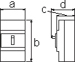 |
a | 52 | 75 | 75 | 75 | 75 | 75 | 75 | 75 | 75 | ||
| b | 96 | 97.5 | 97.5 | 130 | 130 | 130 | 130 | 130 | ||||
| c | 60 | 60 | 60 | 60 | 60 | 60 | 60 | 60 | ||||
| d | 76 | 76 | 76 | 84 | 84 | 84 | 84 | 84 | ||||
| Net Weight (kg) | 0.3 | 0.4 | 0.6 | 0.6 | 0.7 | 0.7 | 0.7 | 0.8 | 0.9 | |||
| Standard Connection Type | Front Terminal | Front Terminal | Front Terminal | Front Terminal | Front Terminal | Front Terminal | Front Terminal | Front Terminal | ||||
| Phase Separator for Line Side | — | — | — | ○ | ○ | ● (*2) | ○ | ● (*2) | ||||
| Interior Accessories |
Test Button Lead Wire | TBL | ○ | ○ | ○ | ○ | ○ | ○ | ○ | ○ | ||
| Alarm Switch | AL | ○ | ○ | ○ | ○ | ○ | ○ | ○ | ○ | |||
| Auxiliary Switch | AUX | ○ | ○ | ○ | ○ | ○ | ○ | ○ | ○ | |||
| Earth Leakage Alarm Sw. | EAL | — | — | — | — | — | — | — | — | |||
| Terminal Block | TB | — | — | — | ○ | ○ | ○ | ○ | ○ | |||
| TB2 | ○ | ○ | ○ | ○ | ○ | ○ | ○ | ○ | ||||
| Exterior Accessories |
Rear-connecting Stud |
STB | — | — | — | STB-2M | STB-2M | STB-2M | STB-3K (50A:STB-2M) | STB-3K (50A:STB-2M) | ||
| BSD | — | — | — | — | — | — | — | — | ||||
| Flush Mounting Base Assembly |
GKW(STB) | — | — | — | ○ | ○ | ○ | ○ | ○ | |||
| GK•GKW(BSD) | — | — | — | — | — | — | — | — | ||||
| Plug-in Mounting Base Assembly |
PK | — | — | — | — | — | — | — | — | |||
| Mechanical Interlock | MIW | — | — | — | MIW-2E | MIW-2E | MIW-2E | MIW-2E | MIW-2E | |||
| Motor-operating Mechanism |
MMK-S | — | — | — | — | — | — | — | — | |||
| MMK-C | — | — | — | — | — | — | — | — | ||||
| Lock Cover | LC | LC-03 | LC-03 | LC-03 | LC-2G | LC-2G | LC-2G | LC-2G | LC-2G | |||
| Handle Lock | HL | — | — | — | HL-2G | HL-2G | HL-2G | HL-2G | HL-2G | |||
| Handle Operating Mechanism |
HA | — | — | — | HA-108 | HA-108 | HA-108 | HA-108 | HA-108 | |||
| HM | — | — | — | HM-S12 | HM-S12 | HM-S12 | HM-S12 | HM-S12 | ||||
| Terminal Cover |
Front Type | TMC | TMC-0G | TMC-0H | TMC-0H | TMC-1 | TMC-1 | TMC-1 | TMC-1 | TMC-1 | ||
| Short Type | — | — | — | TMC-1S | TMC-1S | TMC-1S | TMC-1S | TMC-1S | ||||
| Long Type | — | — | — | TMC-2D | TMC-2D | TMC-2D | TMC-2D | TMC-2D | ||||
| Rear Type | BTC | — | — | — | BTC-1 | BTC-1 | BTC-1 | BTC-1 | BTC-1 | |||
| IEC Rail 35 mm | ● | ● | ● | ○ | ○ | ○ | ○ | ○ | ||||
| Automatic Tripping Device | Full Magnetic | Full Magnetic | Full Magnetic | Full Magnetic | Full Magnetic | Full Magnetic | Full Magnetic | Full Magnetic | ||||
| Trip Button | — | — | — | — | — | — | — | — | ||||
Note
- 1
- ● : Standard ○ : Option
- 2
- Please use right and left poles in case of using ELBs of 3 poles 200V to 1φ2W 200V wiring sysytem.
- 3
- Please connect neutral line to middle pole of ELBs incase of using ELBs of 3 poles 200V to 1φ3W100/ 200V distribution system.
- 4
- Standard fl ush mounting base assembly of up to 400AF are GKW and GK is standard in case of 600AF or more.
- 5
- Installation of phase separators is required in case of types marked(*2).
- 6
- IEC rail is standard installation in case of EB-50E and EB-100E, so installation screws and metal fi ttings are not attached.
- 7
- The accessories marked (*3) can be installed by customers
- 8
- Please state frequency 50 or 60Hz in case of RF-800KN, RF-1000KN, RF-1200KN.