Normal installation is made on the perpendicular plane as shown in Fig. b. As shown in Fig. a, the installation position with an inclination of up to 15° to the left and right and back and forth is permissible.
Limited to models of frames 8C - 125C, side installation, in the condition where it is turned 90° in counterclockwise direction from the normal installation position, can also be made as shown in Fig. c, but in unavoidable cases. However, its life will be shortened by about 20%.
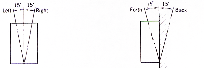
Fig. a Allowable installation angle
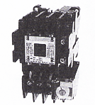
Fig. b Normal installation
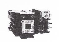
Fig. c Side installation
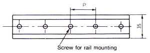
Fig.d
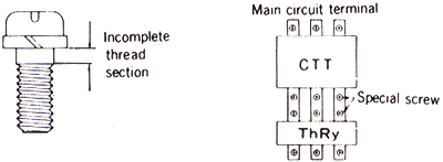
Sometimes a special screw (unitized screw and spring washer) is used in the coupling section of the electromagnetic contactor and thermal overload relay in an electromagnetic starter.
The special screw has an incomplete thread section so when using the thermal overload relay disconnected from the contactor, tighten the screw by inserting a plane washer, etc., so that the incomplete thread section is not screwed into terminal plate.
(1) Interval of screws for rail mounting
Interval of screws for rail mounting -as shown in fig. d- shall be as follows.
- Contactor relays and 8C - 12 frame : P![]() 300mm
300mm
- 20 - 50 frame : P![]() 200mm
200mm
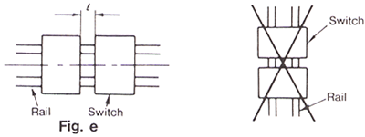
(2) Mounting space of switches
Mounting space of switches -as shown in fig. e- shall be as follows.
- Contactor relay : l![]() 0mm
0mm
- Contactor, starter : l![]() 5mm
5mm
(3) Side installation is not allowed as shown in fig. f.
| Frame | Specifications | Maincircuit | ||||||
|---|---|---|---|---|---|---|---|---|
| Motor capacity 200V Class (kW) | Rated operational current 200V Class (A) | Terminal screw (mm) | Connectable wire (mm2) | Maximum width of usable solderless terminal (mm) | Suitable tightening torque (N-m) | |||
| Electro- magnetic contactor | Thermal overload relay | Electro- magnetic contactor | Thermal overload relay | |||||
| 8C | 2.5 | 11 | M3.5 | (φ1.6) 2 | 7.8 | 1 | ||
| 10C 10B |
3 | 12 | M3.5 | (φ1.6) 2 | 7.8 | 1 | ||
| 11 12 |
3 | 12 | M3.5 | (φ1.6) 2 | 7.8 | 1 | ||
| 20 | 5.5 | 22 | M4 | (φ2) 3.5 | 9 | 1.5 | ||
| 25 | 7.5 | 27 | M5 | (φ2.6) 8 | 10 | 3.5 | ||
| 35 | 11 | 39 | M5 | (φ3.2) 14 | 12.5 | 3.5 | ||
| 50 | 15 | 52 | M5 | 14 | 12.5 | 3.5 | ||
| 65C | 18.5 | 65 | M6 | 22 | 16.5 | 5 | ||
| 80C | 22 | 80 | M6 | 60 | 22 | 5 | ||
| 100C | 30 | 105 | M8 bolt | 60 | 22 | 14 | ||
| 125C | 37 | 126 | M8 bolt | 60 | 27 | 14 | ||
| 150C | 45 | 150 | M8 bolt | 80 | 27 | 14 | ||
| 200C | 55 | 182 | M10 bolt | — | 150 | 37 | 25 | — |
| 250C | 75 | 240 | M10 bolt | — | 150 | 37 | 25 | — |
| 300C | 90 | 300 | M12 bolr | — | 200 | 44 | 45 | — |
| 400C | 115 | 400 | M12 bolt | — | 200 | 44 | 45 | — |
| 600C | 160 | 600 | M12 bolt | — | 325 | 55 | 45 | — |
| Frame | Operation circuit | Xontactor | |||||||
|---|---|---|---|---|---|---|---|---|---|
| Terminal screw (mm) | Connectable wire (mm2) | Maximum width of usable solderless terminal (mm) | Suitable tightening torque (N-m) |
Mounting screw | Suitable tightening torque (N-m) | ||||
| Electro- magnetic contactor | Thermal overload relay | Electro- magnetic contactor | Thermal overload relay | Screw diameter (mm) | Number of screws | ||||
| 8C | M3.5 | (φ1.6) 2 | 7.8 | 1 | M4 | 2 | 1.5 | ||
| 10C 10B |
M3.5 | (φ1.6) 2 | 7.8 | 1 | M4 | 2 | 1.5 | ||
| 11 12 |
M3.5 | (φ1.6) 2 | 7.8 | 1 | M4 | 2 | 1.5 | ||
| 20 | M3.5 | (φ1.6) 2 | 7.8 | 1 | M4 | 2 | 1.5 | ||
| 25 | M3.5 | (φ1.6) 2 | 7.8 | 1 | M4 | 2 | 1.5 | ||
| 35 | M3.5 | (φ1.6) 2 | 7.8 | 1 | M4 | 2 | 1.5 | ||
| 50 | M3.5 | (φ1.6) 2 | 7.8 | 1 | M4 | 2 | 1.5 | ||
| 65C | M3.5 | (φ1.6) 2 | 7.8 | 1 | M4 | 2 | 1.5 | ||
| 80C | M3.5 | (φ1.6) 2 | 7.8 | 1 | M5 | 2 | 3.5 | ||
| 100C | M3.5 | (φ1.6) 2 | 7.8 | 1 | M5 | 2 | 3.5 | ||
| 125C | M3.5 | (φ1.6) 2 | 7.8 | 1 | M6 | 2 | 5 | ||
| 150C | M3.5 | (φ1.6) 2 | 7.8 | 1 | M6 | 2 | 5 | ||
| 200C | M3.5 | (φ1.6) 2 | 7.8 | 1 | M8 bolt | 4 | 14 | ||
| 250C | M3.5 | (φ1.6) 2 | 7.8 | 1 | M8 bolt | 4 | 14 | ||
| 300C | M3.5 | (φ1.6) 2 | 7.8 | 1 | M8 bolt | 4 | 14 | ||
| 400C | M3.5 | (φ1.6) 2 | 7.8 | 1 | M8 bolt | 4 | 14 | ||
| 600C | M4 | M3.5 | (φ1.6) 2 | 7.8 | 1.5 | 1 | M8 bolt | 4 | 25 |
Remark